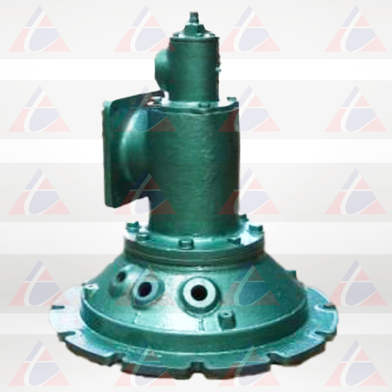
FIRE ALL GAS BURNER - 1514

These hardy nozzle-mix burners have been used for many years on high temperature furnaces such as those for forging steel, melting aluminum or brass, and reheating steel bars or ingots…and on low temperature ovens and air heaters. Their sealed-in construction allows maximum efficiency through close control of air/gas ratio, furnace atmosphere, and furnace pressure–all contributing to better product quality. 1514 Fire All Burners, as the name suggests, are appropriate for an extensive industrial heating applications. Nominal capacities range from 6 to 84 mkcal/hr.
Fire All Gas Burner
COMBUSTION PERFORMANCE
1514 Burners are better with 200% or more excess air. They may also be operated with excess fuel without forming carbon if additional combustion air is available in the furnace near the burner. Excess fuel limit with heavy oil is 50% as atomization deteriorates at richer ratios. Burners can be turned down to atomizing air only, but stability limits vary depending on burner size, grade of oil, and furnace atmosphere. For prolonged operation on atomizing air only in furnaces over 1200o C specify an alloy burner nose. Burners are suitable for some preheated combustion air applications (up to 350o C). Oil viscosity at the burners should not exceed 90 seconds R.W.I; oil pressure at the Ratio controller should be between 25 and 30 psi. Minimum atomizing air pressure at the burner is 24”wg for light oil, 42”wg for heavy oil.
BURNER BLOCKS/INSTALLATION
Burner blocks are cast refractory rated for 1500o C furnace temperature. They are replaceable in the field, except for the 1514-10A whose mounting must be returned to the factory for burner block replacement (or purchase a spare mounting plate with a burner block cast onto it). Burner blocks should be supported securely in the furnace wall by a layer of castable refractory (not insulation) at least 9″ thick all around the burner block, extending back to the furnace shell and securely anchored to it. For furnace walls thicker than the length of the burner block, the tunnel beyond the end of the burner block should be flared 30-45° from the center line, starting at the OD of the burner block.
JACKETED BURNER BLOCKS
1514 Burners are available with support jackets around the burner block for applications where the burner block is not supported by furnace refractory. Jackets are available in three different metals and have maximum temperature ratings for each. They must be protected with sufficient insulation so as not to exceed rated temperature. Maximum temperature rating for jacket metals depends upon frequency of heat-up/cool-down cycles. As an example, batch annealing furnaces that are heated and cooled every day should use the “intermittent exposure” ratings. Continuous annealing furnaces that remain at the same temperature for months at a time, can use the higher “continuous” rating.
| Designation | JacketMetal | Continuousmax.temp. | Intermittent exposure |
|---|---|---|---|
| 1514- A1 | carbon steel | 350OC | 350OC |
| 1514- A2 | 304 stainless | 850OC | 800OC |
| 1514- A | 3 309 stainless | 1000OC | 950OC |
FLAME SUPERVISION
Flame safeguards are recommended for all installations. An ultraviolet cell will monitor pilot or main flame. Pilots must be interrupted after a preset ignition period (usually 15 seconds) so flame detectors monitor main flame only.
WORKING NATURE
Control: Normally, air primary with a cross-connected, pressure balance regulator. For maximum turndown, use a (biased) Regulator, or throttle gas only. To protect burner from heat damage, do not set air pressure below 2”wg in an 850o C furnace, or below 3”wg at 1000o C (whether gas is on or off). Gas pressure requirement: About 2”wg at the burner for natural gas on stoichiometric ratio; about 1/5 of the air pressure for coke oven gas. Preheated air: 1514 Burners are suitable for some applications with air preheated to 400o C.
| LIST 1.COMBUSTIONAIR CAPACITITES Scfh (Standard Cubic feet/hr) Air Pressure Drop Across the Burner in inches of WGP | |||||||||
|---|---|---|---|---|---|---|---|---|---|
| Burner Designation | Approx. Flame length air/fuel ratio inmm | Availableexcess air ratio setting 27"wg | |||||||
| 1 | 2 | 9 | 6 | 10 | 21 | 28 | |||
| 1514-6A | 1180 | 3710 | 8300 | 9100 | 10500 | 12900 | 14900 | 1368 | 300 |
| 1514-7A | 1930 | 6100 | 13600 | 15000 | 17200 | 21000 | 24400 | 1520 | 650 |
| 1514-8AA | 3350 | 10600 | 23700 | 26000 | 30000 | 36700 | 42400 | 2432 | 450 |
| 1514-9AA | 5550 | 17600 | 39200 | 43000 | 49600 | 60500 | 70000 | 2736 | 250 |
| 1514-10A | 11600 | 36600 | 82000 | 89500 | 104000 | 127000 | 146000 | 4864 | 700 |
| 1514-11A | 17300 | 54500 | 122000 | 135000 | 154000 | 189000 | 218000 | 5776 | 350 |

