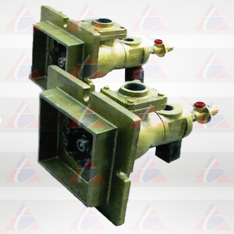
EXCESS AIR LIGHT OIL BURNER - 2422

2422 Excess Air Light Oil Burners are commonly used on heat treat and non-ferrous melting furnaces, kilns, ovens, air heaters, dryers, chemical process equipment, and other applications where superior temperature uniformity is required. These sealed-in, nozzle-mix burners for gas and/or light oil are stable on stoichiometric ratio, with huge amounts of Xces air, or with up to 50% Xces fuel (provided additional air for combustion is in the furnace near the burner.
Excess Air Light Oil Burner
APPLICATION TEMPERATURE
The 2422 burners can be used with chamber temperatures upto 1110o C. If furnace temperature could rise above 850oC after shutdown, some air should be maintained through the burner to prevent overheating.
| LIST I. AIR CAPACITIES*Scfh (Standard Cubic Feet perHour) | |
|---|---|
| Burner Designation | 28” wg air at burne |
| 2422-2A | 2 800 |
| 2422-3A | 4 000 |
| 2422-4A | 6 500 |
| 2422-5A | 10 100 |
| 2422-6A | 15 500 |
| 2422-7-AA | 27 200 |
| 2422-8-AA | 33 000 |
| 2422-9-AA | 44 500 |
| * Includes primary and secondary air. | |
PERFORMANCE
Burners can be lighted at rich, lean, or correct air/fuel ratio, then immediately turned to high fire. Required gas pressures are low: 2”wg at the burner for coke oven gas, less for natural gas. Required oil pressure at the burner is nearly zero, but a pressure drop of about 10 psi should be taken across the Precise Control Valve.
The most common air fuel control system for 2422 Burners uses a cross-connected regulator and Ratio controller. When appropriate for the application, flow balancing systems or fuel only control is very satisfactory. If furnace temperatures after shutdown rise above 950oC, pass some air through burner to prevent overheating. During gas performance, use at least 7”wg atomizing air to cool atomizer (full atomizing air may be used); or for extended periods of performance on gas, atomizer can be with drawn and stored: Use a back plate and gasket to seal rear of burner.
LIGHTING / FLAME SUPERVISION
A Pilot Set generally is used to light 2422 Burners. On gas, direct spark ignition of the burner is available. A manual torch can be used in some applications. Burners accept ultraviolet (UV) scanners for monitoring pilot or main flame. A flame rod can be used to monitor pilot or main gas fire. When using flame supervision, an interrupted pilot is required. If using direct spark ignition, turn off spark after burner lights. An observation port is furnished with all burners. A lighter hole cover is supplied if a pilot is not ordered. Positions of pilot, flame detector, and observation port are interchangeable as long as pilot and flame detector are mounted in adjacent holes.
XCES AIR
Xces air can improve temperature uniformity by avoiding hot spots in front of burners, by churning furnace atmosphere to reduce stratification, and by creating positive furnace pressure to eliminate cold air infiltration. Xces air can give very high effective burner turndown. Thus a furnace used for high temperature work (such as heat treating at 950oC) with burners firing on air/fuel ratio can also be used for low temperature jobs (such as drawing or drying at 300o C) with burners firing on lean ratio.
CONSTRUCTION FEATURES
Air and gas inlets can be rotated in 90° both CW& ACW Direction, but air and gas pipes should be brought in from the top or side to prevent oil dripping into them. Mounting plates are cast iron. Burner Blocks are 9″ long for thicker furnace walls, lining beyond end of tile should be flared at least 30° included angle, starting at tile OD. Extension tiles are not recommended. For installation convenience, burner body can be separated fromthe mounting plate and tile assembly. But burner block must be set in the wall with pilot and flame detector notches in proper location relative to intended burner body position.
JACKETED BURNER BLOCKS: 2422 Burners have a carbon steel jacket around the burner block for applications where there is no furnace refractory to support tiles and where temperatures surrounding the jacket will not exceed 450o C. Stainless jackets are available for higher temperatures.
LIST II - COMBUSTION AIR CAPACITITES in scfh (not including atomizing air) |
|||||||||
|---|---|---|---|---|---|---|---|---|---|
| Burner Designation | Air Pressure Drop Across Burner in inches of WGP | Approx. flame lengths in millimeter with 28”wg Main air (in open furnace) | |||||||
| 1 | 2 | 8 | 10 | 14 | 21 | 28 | Gas | Oil | |
| 2422-2A | 160 | 520 | 1160 | 1270 | 1470 | 1800 | 2100 | 0152 | 0456 |
| 2422-3A | 280 | 890 | 1980 | 2160 | 2500 | 3050 | 3550 | 0456 | 0608 |
| 2422-4A | 460 | 1450 | 3240 | 3540 | 4100 | 5000 | 5800 | 0608 | 0760 |
| 2422-5A | 750 | 2370 | 5300 | 5800 | 6700 | 8150 | 9450 | 0760 | 0760 |
| 2422-6A | 1180 | 3700 | 8300 | 9100 | 10500 | 12900 | 14800 | 0912 | 1216 |
| 2422-7AA | 2070 | 6550 | 14600 | 16000 | 18500 | 22700 | 26200 | 1824 | 1824 |
| 2422-8AA | 2580 | 8150 | 18200 | 19900 | 23000 | 28200 | 32600 | 1824 | 1520 |
| 2422-9AA | 3320 | 10500 | 23500 | 25800 | 29700 | 36400 | 42000 | 2128 | 1824 |
LIST III - ATOMIZING AIR CAPACITITES in scfh |
||||||
|---|---|---|---|---|---|---|
| Air pressure drop across burner in inches of WGP | ||||||
| Burner Designation | 24 | 28 | 31 | 34 | 38 | 41 |
| 2422-2A, -3A,-4A | 500 | 520 | 560 | 600 | 620 | 650 |
| 2422-5A | 640 | 690 | 720 | 760 | 800 | 840 |
| 2422-6A | 800 | 850 | 910 | 950 | 1000 | 1050 |
| 2422-7AA, 8AA | 870 | 930 | 990 | 1040 | 1100 | 1150 |
| 2422-9AA | 2650 | 2840 | 3000 | 3170 | 3320 | 3580 |

