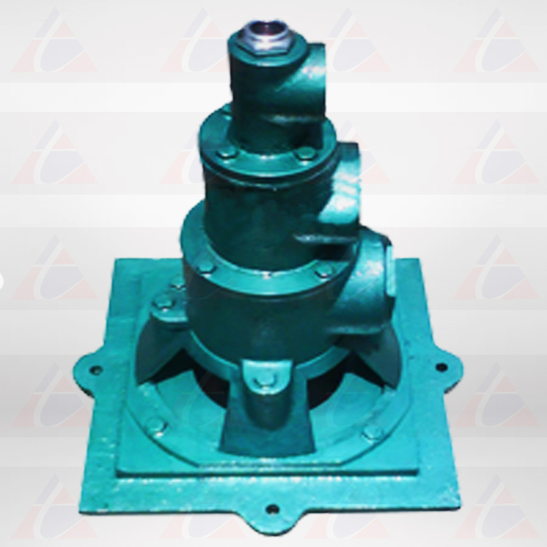
DUAL FUEL BURNER - 3562
DUAL FUEL BURNER - 3562

Series 3562 Dual-Fuel Burners are designed to give maintenance-free operation using heavy oil, light oil, or gas. There are no “Frills”on this burner – it has a heavy cast iron body of clean design that avoids clogging even when used on tough jobs such as forge furnaces fired with heavy oil.
BURNER CAPACITY
The total air capacity of the burners is listed under list I for single blower supplying at 20”wg combustion air and 24”wg atomizing air for light oil operation and 34”wg combustion air and 38”wg atomizing air for heavy furnace oil operation. Use list II and III when selecting separate blowers for combustion and atomizing air. For sizing blowers or burners at other pressures, add figures from the List II and III to get total capacity. Capacities shown in list II is for operation on gas with the air shuttled closed. On oil operation these capacities are increased 20% the additional air supplied through the atomizing air connection. When burning either gas or oil with the shutter open, burner capacities may be doubled if furnace conditions assure sufficient secondary air.
BURNER OPERATION
Oil with a viscosity of 70 to 90 seconds Redwood I and a pressure between 25 and 30 psi, should be supplied to an Air/Oil ratio controller which will deliver oil to the burner at a pressure proportional to the main air pressure, thus maintaining the correct air/oil ration at all firing rates. The atomizing air pressure at the burner may be as low as 28”wg when using distillate oil, 38”wg when using heavy oil. The 3562 burners can operate on any gas of 2000 to 12800 kcal per cubic feet heating value. Switching from gas to oil operation or oil to gas may be done quickly without furnace shutdown, simply by turning off one fuel valve and opening the other.
BURNER CONSTRUCTION
The heavy cast iron body can stand much abuse. All internal parts of the 3562 burner are machined. The smooth surfaces stay free of oil deposits and dirt, thus greatly minimizing the need for cleaning, oil is, put though the burner in a straight passage having a large cross-sectional area permitting visual inspection for clogging and easy clean out if necessary. The burner oil valve is a non-plugging V-port oil valve which produces small and uniform flow rate changes throughout the 180o C sweep of the control handle.
LIST I. AIR CAPACITIES in CFH |
||||
|---|---|---|---|---|
| Burner Designation | 3562-3A | 3562-4A | 3562-5A | |
| Air Pressures at Burner | Combustion 24”wg; Atomising 28”wg | 4735 | 5935 | 10630 |
| Combustion 40”wg; Atomising 44”wg | 6320 | 7670 | 13640 | |
LIST II. COMBUSTION AIR CAPACITIES in CFH |
|||||||||||||
|---|---|---|---|---|---|---|---|---|---|---|---|---|---|
| Burner Designation | Air pressure at Burner in inches of WGP | ||||||||||||
| 1 | 2 | 3 | 5 | 7 | 9 | 10 | 14 | 17 | 21 | 24 | 28 | 35 | |
| 3562-3A | 575 | 1150 | 1625 | 1900 | 2300 | 2575 | 2815 | 3250 | 3635 | 3800 | 4300 | 4600 | 5150 |
| 3562-4A | 725 | 1450 | 2050 | 2500 | 2900 | 3250 | 3525 | 4100 | 4580 | 5000 | 5420 | 5800 | 6500 |
| 3562-5A | 1156 | 2312 | 3270 | 3270 | 4625 | 5175 | 5660 | 6540 | 7300 | 8000 | 8650 | 9250 | 10350 |
LIST III. ATOMISING AIR CAPACITIES in CFH |
||||||
|---|---|---|---|---|---|---|
| Burner Designation | Air pressure at Burner in inches of WG | |||||
| 24 | 28 | 31 | 35 | 38 | 41 | |
| 3562-3A | 935 | 1000 | 1060 | 1120 | 1170 | 1220 |
| 3562-4A | 935 | 1000 | 1060 | 1120 | 1170 | 1220 |
| 3562-5A | 2630 | 2810 | 2980 | 3150 | 3290 | 3430 |

